Beads-on-Leads (2761015112*)
61 BEAD ON LEAD
61 Material™
Suppression Components
Board Component
Printer Friendly Data Sheet
Catalog Drawing
3D Model
Check Stock

Part Number: 2761015112
61 BEAD ON LEAD
Explanation of Part Numbers:
– Digits 1 & 2 = Product Class
– Digits 3 & 4 = Material Grade
– Last digit 1 = Bulk Packed 2 = Taped and Reeled
Ferrite suppression beads are supplied assembled on tinned copper wire for automated circuit board assembly.
– Wires are oxygen free high conductivity copper with 100% matte tin plating over a nickel undercoating. The resistance of the wire is 3.5 mOhm for the 22 AWG and 2.2 mOhm for the 20 AWG wire.
Packaging Options:
– Beads-on-leads can be supplied bulk packed. The last digit of bulk packed parts is a “1”. Parts with a “2” as the last digit of the part number are supplied taped and reeled per IEC 60286-1 and EIA RS-296-F standards. Taped and reeled parts are supplied 4500 pieces on a 14″ reel. Taping details: Component pitch 5 mm. Inside tape spacing 52.5 mm. Tape width 6 mm.
– Our “Bead-on-Lead Suppression Kit” (part number 0199000028) is available for prototype evaluation.
For any bead-on lead requirement not listed here, feel free to contact our customer service group for availability and pricing.
Weight: 0.4 (g)
| Dim | mm | mm tol | nominal inch | inch misc. |
| A | 3.5 | ±0.25 | 0.138 | _ |
| B | 62 | ±1.50 | 2.44 | _ |
| C | 5.25 | ±0.25 | 0.207 | _ |
| D | 0.65 | _ | 0 | 22 AWG |
| Reel Information | ||||
| Tape Width mm | Pitch mm | Parts 7" Reel | Parts 13" Reel | Parts 14" Reel |
| 6 | 5 | _ | _ | 4500 |

Chart Legend
+ Test frequency
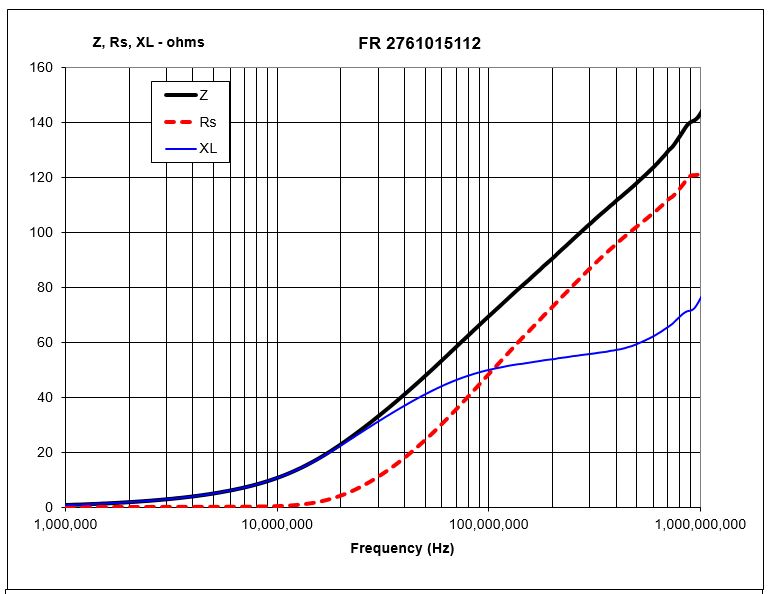
| Typical Impedance (Ω) | |
| 100 MHz | 70 |
| 250 MHz+ | 97 |
| 500 MHz+ | 118 |
| 1000 MHz | 143 |
Beads-on-leads are controlled for impedances only. Minimum impedance values are specified for the + marked frequencies. The minimum impedance is typically the listed impedance less 20%.
The impedance of the 73 & 43 beads-on-leads are measure on the E4990A Impedance Analyzer. The 61 beads-on-leads are tested for impedance on the E4991A / HP4291B Impedance Analyzer.
| Typical Impendance (Ω) | |
| 100 MHz | 62 |
| 250 MHz+ | 85 |
| 500 MHz+ | 97 |
| 1000 MHz | 105 |
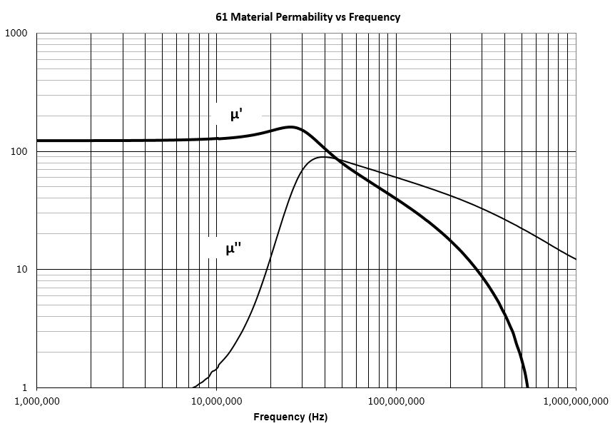
A high frequency NiZn ferrite developed for a range of inductive applications up to 25 MHz. This material is also used in EMI applications for suppression of noise frequencies above 200 MHz. Excellent stability characteristics.
Strong magnetic fields or excessive mechanical stresses may result in irreversible changes in permeability and losses.
Available in 61 material™:
EMI Suppression Beads
Beads On Leads
SM beads
Wound Beads
Multi-Aperture Cores
Round Cable Snap-Its
Toroids
Rods
Antenna/RFID
Rods
Round EMI Suppression Cores
61 Material™ Characteristics
| Property | Unit | Symbol | Value |
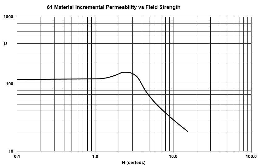
| Initial Permeability @ B < 10 gauss | µi | 125 | |
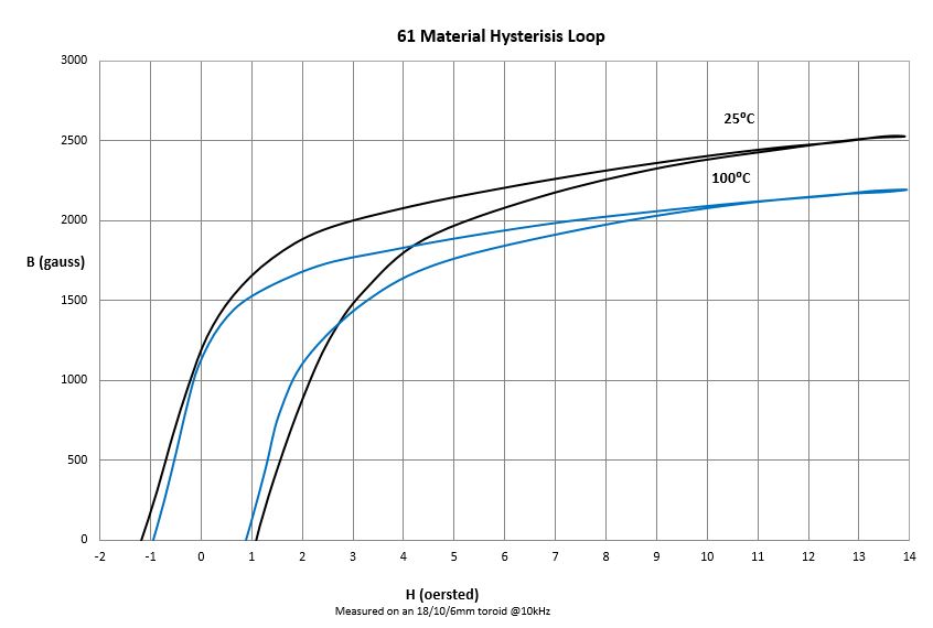
| Flux Density @ Field Strength | Gauss Oersted |
B H |
2500 15 |
| Residual Flux Density | Gauss | Br | 1000 |
| Coercive Force | Oersted | Hc | 1.2 |
| Loss Factor @ Frequency | 10 -6 MHz |
Tan δ/ µi | 90 10 |
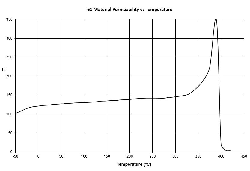
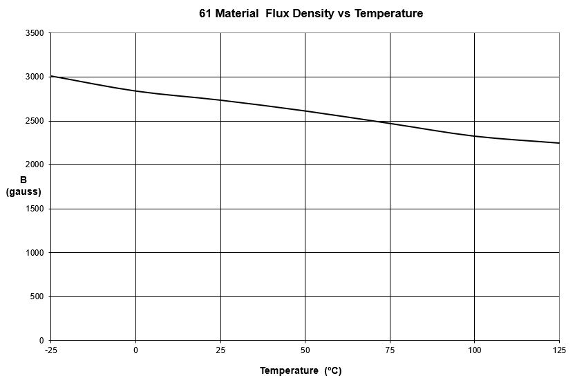
| Temperature Coefficient of Initial Permeability (20 -70°C) | %/°C | .10 | |
| Curie Temperature | °C | Tc | >300 |
| Resistivity | ohm-cm | ρ | 1×10⁸ |
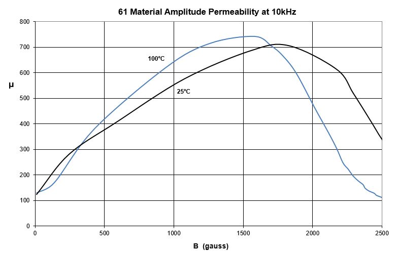
**** Characteristic curves are measured on standard Toroids (18/10/6 mm) at 25°C and 10 kHz unless otherwise indicated. Impedance characteristics are measured on standard shield beads (3.5/1.3/6.0 mm) unless otherwise indicated.
Material Safety Data Sheet (MSDS)
Click here to download Complex Permeability vs. Frequency (CSV)
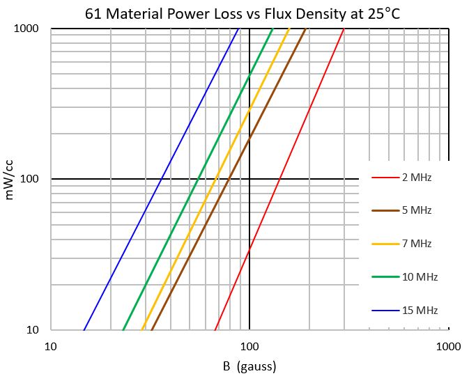
Click here to download 61 Material Power Loss Density vs. Flux Density at 25°C
Ferrite Material Constants
Storage and Operating Temperature